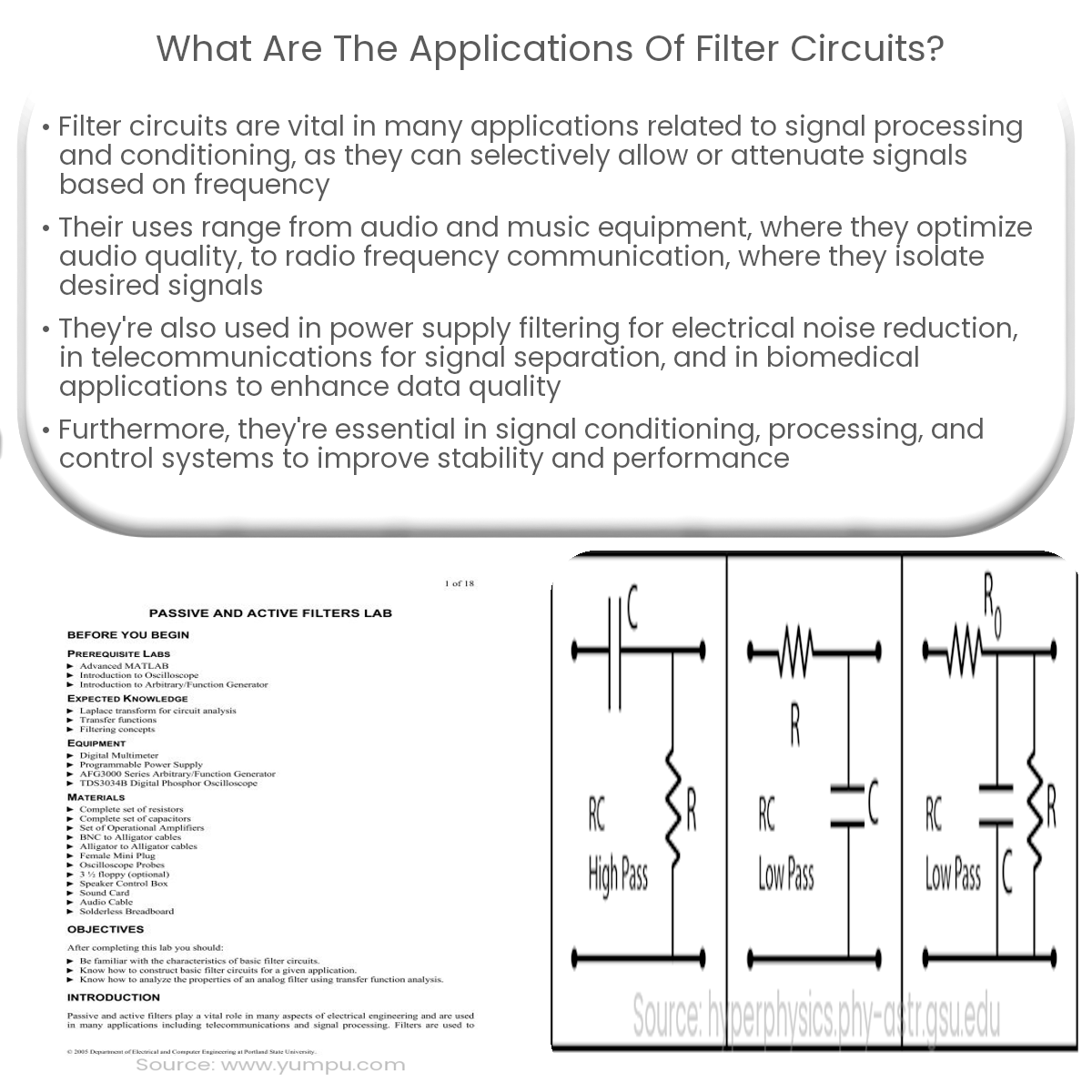
Active Audio Filter Board Audio Amplifier Electronic Circuit Projects Circuit Diagram Active notch filters were actively used during the earlier decades for amplifier and audio applications for eliminating of 50- and 60-Hz hum interferences. These networks have been although somewhat awkward from the standpoints of center notch frequency (f0) tuning, balance, and consistency. A filter is a device that passes electric signals at certain frequencies or frequency ranges while preventing the passage of others. — Webster. Filter circuits are used in a wide variety of applications. In the field of telecommunication, band-pass filters are used in the audio frequency range (0 kHz to 20 kHz) for modems and speech processing.

The above discussions shows how simply anybody can calculate and design a high-pass filter circuit quickly for a particular application which could be a treble control circuit, a 10 band graphic equalizer or a home theater circuit etc. How Low Pass Filters Work

10 Useful Active Filter Circuit Diagrams Explored
A filter circuit is a device that permits the D.C. For successful implementation in a variety of electronic systems, a thorough comprehension of their guiding principles and meticulous evaluation of design parameters are essential. In a variety of electronic applications, filter circuits are essential for modifying and enhancing electrical signals.
An audio circuit collection, Part 1 Introduction This is the first of two articles on audio circuits. New oper-ational amplifiers from Texas Instruments have excellent audio performance and can be used in high-performance applications. There have been many collections of op amp audio circuits in the past, but all of them focus on split-supply

PDF How to Design 10 kHz filter. (Using Butterworth filter design ... Circuit Diagram
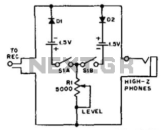
Passive, resistor-capacitor filters are among the most basic audio filters. RC Filters. The design for a basic L-section resistor-input RC passive filter is shown in Figure 1-a, in which the capacitor C1 functions like an open circuit at lower frequencies and like a short circuit at higher frequencies.
The most useful filters with ease of use and best all-around performance are the Sallen Key active filters. Sallen Key filters are two-pole filters, meaning they have two reactive components (capacitors). All of the circuits below are based on this design. Low Pass Filter. In a low pass filter, frequencies above a certain point are blocked:
PDF Active Filter Design Techniques Circuit Diagram
Next, high pass filter is designed to attenuate frequencies from 0 to 9.75 kHz. Cut-off frequency is set to 9.75 kHz and standard capacitor value for audio circuit design chosen to be 0.01 micro Farads. To calculate Resistor values for High pass filter Equation 2 is used. Where: m = magnitude coefficient f c = 9.75 kHz Cs = 0.01 micro Farads D volved in electronic circuit design to have the ability to develop filter circuits capable of meeting a given set of specifications. Unfortunately, many in the electronics field are uncomfortable with the subject, whether due to a lack of familiarity with it, or a reluctance to grapple with the mathematics involved in a complex filter design