Low Pass Filter Schematic Diagram for Electronics Design Circuit Diagram The following images depict the standard opamp based low pass filter circuits. The first one needs to be powered by a dual supply, and the second one works using a single supply voltage. Designing a Customized Low Pass Filter Circuit

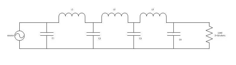
The formula and schematic for the LC low pass filter: Let's analyze a low pass filter with a practical example : Q. Design a low pass filter having cutoff frequency 'fc' = 75MHz and Vin = 5 volts using RC filter? Solution: given -> f = 75Mhz. R = 100 Ω(assumed)——-

Design, Schematic, advanced guide Circuit Diagram
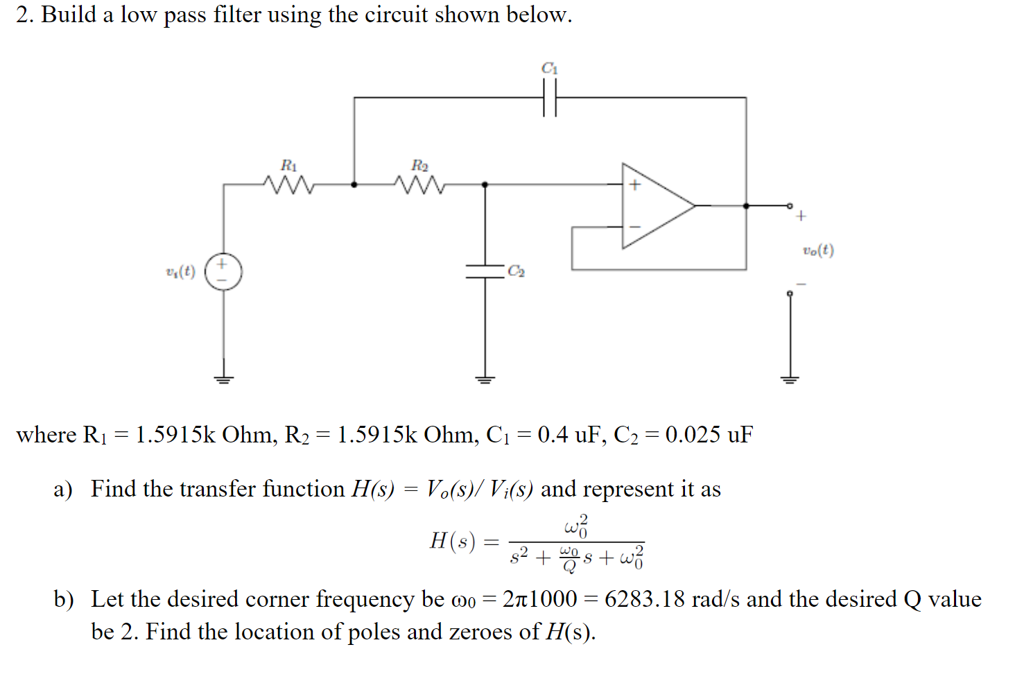
Designing a low-pass filter circuit may seem straightforward on the surface, particularly when approached from an instructional perspective. However, if you're in the expert's shoes, you'll understand how rigorous the thought process is to design an effective lowpass filter circuit. Even the most experienced RF and electrical engineers Active Low-Pass Filter Design Jim Karki AAP Precision Analog ABSTRACT This report focuses on active low-pass filter design using operational amplifiers. Low-pass filters are commonly used to implement anti-aliasing filters in data acquisition systems. Design of second-order filters is the main topic of consideration.
To surmount this problem, active circuit designs were introduced. When a passive low pass filter is connected to an Op-Amp either in inverting or non-inverting condition, it gives an active low pass filter design. The connection of a simple RC circuit with a single Op-Amp is shown in the image below.. First Order Active Low Pass Filter with the frequency response Whether you're designing an entire sound system complete with a bass boost, or just want to remove high-frequency noise, the low-pass filter calculator can help you create the perfect low-pass filter circuit for your needs. Read on to learn: What a low-pass filter is; The difference between passive and active low-pass filters; and